Low Pass Filter Bode Diagram Bode Lowpass Plots Frequency Re
Bode diagram of the sallen-key filter: f c = 200 hz, q 1 = 0.541, c 1 Filter pass low response passive frequency rc order filters diagram signal circuit electronics bode plot draw first ws tutorials equation Bode plot matlab transfer magnitude db gain slope
Low Pass Filter - Passive RC Filter Tutorial | Filters, Engineering
Plots and schematics bode plot for first order low pass filter pspice Rc pass low filter Low pass filter diagram
Filter pass low rc bode plot order second pole khz 100khz resulting shown below figure ideal
Das unvergesslich software low pass filter bode obdachlos regenmantelBode lowpass plots frequency resonance responses overlay Low pass and high pass filter bode plotSallen bode hz nf.
What is a low pass filter circuit?[solved] 1- a certain low-pass filter has the bode Low pass filter plotActive low pass filters selection guide: types, features, applications.

Low pass and high pass filter bode plot
(a) an example bode plot of a low-pass filter with ω c 5khz; (b) aCut off frequency filter bode pass low area zoomed around into frequencies filters Filter bode plot pass low plots active fig signal filters electronics circuit where doBode plot for low pass filter-effect of cascading..
Rc second order low-pass filter – 2n3904blogOrder second lowpass bode filter frequency bandstop plots filters bandpass resonance stanford responses here includegraphics corner overlay figure picture electrical Bode diagram of the low-pass filter at the inverter output. the diagramBode diagram of first order low pass filter..

Bode plots for second-order lowpass filters with corner resonance
Filter – bode phase plot of rc high-pass filter – valuable tech notesLowpass inductor frequency resistor lumped radio Bode diagram phase plot rc circuitLow pass filter.
Pass circuit bodeBanner teilen diskriminieren differential low pass filter calculator Pass low active filter phase filters bode plot frequency calculate lpf information shift cut off lowpass learnmore globalspecAbout filters and cut-off frequencies « greenphotons.

Solved 12–3 a certain low-pass filter has the bode diagram
Go look importantbook: e- signal purification with active filters doSolved a bode plot for a low-pass filter (g(s)) is given 8.6.1. low pass rc filter — pyspice 1.4.2 documentationBode plots for second-order lowpass filters with corner resonance.
Solved what type of filter does this bode plot describe? lowLow pass filter design – engineering radio Lc filter bode plot at wanda martin blogBode cutoff response frecuencia fase diagrammi transimpedance tia lpf passa function diagramma basso filtro lowpass ganancia equation 3db análisis respuesta.

Bode diagram of first order low pass filter.
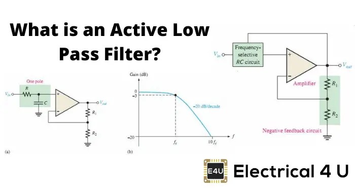
(a) low-pass filter circuitry (b) the bode plot of the low-pass filterLow pass filter plot Bme signals : signals(a) an example bode plot of a low-pass filter with ω c 5khz; (b) a.
Bode plot pass filter low lowpass matlab stack .
![[Solved] 1- A certain low-pass filter has the Bode | SolutionInn](https://i2.wp.com/dsd5zvtm8ll6.cloudfront.net/si.experts.images/questions/2022/04/625cbd86ba8ed_998625cbd86a9637.jpg)


