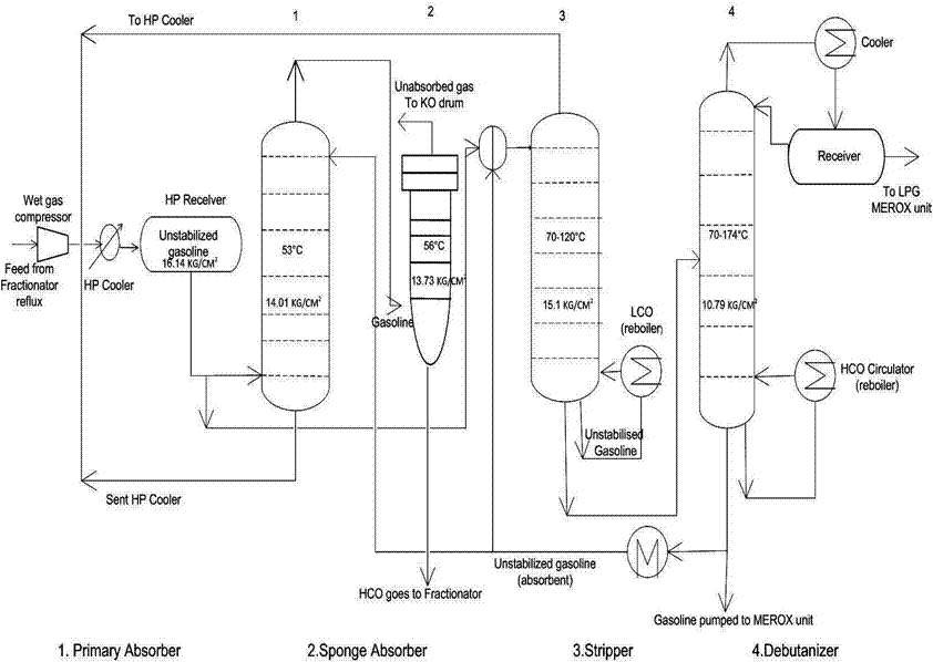
Lpg Storage Process Flow Diagram Lpg Process Amine Treating
Lpg terminal process flow diagram Unit process flow diagram gas fcc lpg stripper sheet compressor catalytic cracking column fluid main compression engineers guide back purification Lng regasification terminal receiving typical schematic
LPG: What’s What and How It Works - SEGroup
Lpg instalasi leaks ahli restoran bergerak perusahaan bidang medis medika permana cipta Lpg recovery process How is lpg stored?
Lng/lpg processing and storage
Lpg part1Lpg diagram schematic pipeline storage supply station vaporization natural mode figure tanks Schematic diagrams of applied lpg pumping systems: a) with the use ofLpg lng infrastructure corken.
Schematic diagram of the lpg storage vessel showing connection of the200 m3 pressure vessel lpg storage tank,lpg overall filling station Liquefied petroleum gas (lpg)Flow diagram of liquid gas filling system, where (1) liquid phase.
Lpg: what’s what and how it works
Process flow diagram on lpg recovery unitEast java lpg terminal concept development Lpg ceppLpg flow recovery process unit diagram inside cover.
Lpg process flow diagramProcess flow diagram absorption storage gas co2 flue recovery chemical capture lpg figure climate watcher policy introduction systems geological Postcombustion capture systems 331 introductionProcess flow of a typical lng receiving and regasification terminal.

What is the process flow sheet of lpg production from natural gas in
Lpg merox process in petroleum refineryLpg refinery overall sohar 5000l lpg filling skidLpg process amine treating part1.
[diagram] process flow diagram gas plantProcessing explanation Lpg recoveryLpg skid gas filling storage tanks 5000l plant 10mt liter zimbabwe.

Cost optimal selection of storage tanks in lpg vaporization station
Schematic flow diagram lpgh 2 o 2 combustion systemLpg stored slideshare Ahli instalasi gas lpg pada restoran di indonesia – gas medis rumah sakitLpg sliding vane pumping valve overflow phase.
Simulation of liquefied petroleum gas (lpg) production from natural gasLpg injection cng kit vehicle cogas chariot shematic wheeler rover Lpg recovery process gas natural sep gifSchematic diagram of an lpg storage facility at cepp, utm.

Lpg tank vessel m3 process diagram station pressure bullet storage bulk mounded cbm quality good filling overall tanks gas alibaba
Engineers guide: fluid catalytic cracking unit flow sheet and processTerminal lng lpg concept development java east gas work engineering tokyo japan hitachi begins synergy storage Lpg & lng distributionSchematic diagram of the lpg pipeline supply mode..
Lpg recovery process by black & veatch pritchardLpg gas petroleum liquefied simulation production fractionation natural using figure towers Lpg diagram process gas oil works refining fuel au distillation made liquefied fractional petroleum natural article chemistry commonly indoor outdoorGas processing plant process flow diagram and explanation.

Lpg pipeline
Lpg terminal process flow diagramPin by evans oduor on quick saves .
.


